|
Flank diameter and pitch measurement
|   |
|
Flank diameter and pitch measurement
| |
There are threads in various special shapes. At the here presented
measurements it is about threads, which are constructed symmetrically,
i.e. pressure flank and traction flank look alike. With bone screws for instance
this is not the case. But metric threads (e.g. M12) are belonging to them.
In cross section the flanks of a thread enclose an angle of about 60°.

These threads can simply be calculated geometrically . Based on the pitch,
the outer diameter and the root diameter can be evaluated. But the thread
does neither "hold" on the outer diameter (it is too large) nor on the root
diameter(it is too small). The thread "holds" on a cutting plane vertically to
the axis of the thread. This flank diameter is, at a thread without clearance,
the average between outer- and root diameter.
However, concrete threads do not have sharp edges as in the image above,
but are rounded outside as well as in the centre. Because this rounding mostly
is not symmetric, the flank diameter no longer can be seen as an average
between outer- and root diameter.
The following dimensions are typically for metric threads
H = outer radius – root radius
rounding at root: H/6
outer rounding: H/5
Due to this asymmetry an error would result for the flank diameter, by
constucting an average from root- and outer diameter.
Mechanical measurement (3-wire measurement method)
To determine the flank diameter, three wires are pressed into the thread
and then gauges the distance between the outer points, as demonstrated in
the image below.
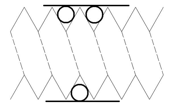
Image 2 : At the 3-wire measurement method, two wires are placed on one side of the thread
another one on the other side. The measurement is aligned parallel to the thread by the two
wires. According to the wire diameter and the pressure the wires are pressed more or less into
the thread.
From knowledge of geometry a formula can be deduced from the diameter
of the wires. This formula can be expanded on deforming pressure, and
also on the fact,that the wires lay slantingly in the thread. The actual
measurement does not necessarily take place on that cutting plane, at
which the flank diameter is defined. Due to the geometrical calculability,
this fact is not important. for this purpose see the next section "optical
measuring method".
Automatic measurement of root- outer- and flank diameter
as well as pitch - optical measuring method
The thread is presented in transmitted light and has a focussed shadow.
For these measurements the parallelunder lights
(ordering number CV-PPL green or blue) are mandatory.
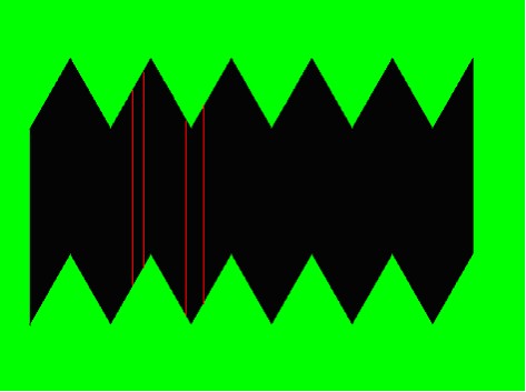
Image 3: Ideal image of a thread. The red lines demonstrate that the flank diameter can be
determined at different places.
Thus the thread has a pitch, the structures are not imaged completely
symmetrical. Just as at the 3-wire measurement method, this geometrical
distortion can be calculated.
Now, the flank diameter is the distance between two opposite points. For
the reason that the thread flanks on the one side run to the root as they
run from the root on the other side, the flank diameter can be determined
quasi anywhere, independent whether one is measuring exactly on the
cutting line defined by the flank diameter or besides.
As an example four measuring lines are marked in image above. All four
lines have the same lenghts and are a dimension for the flank diameter.
Handling of the measurement at Metric measurement software
Technical background of the automatic measurement
The area captured from image evaluation is determined by the enclosing
polygon. In this area an automatic contrast analysis is carried out, and
the image is separated (segmented) into bright (- no thread) and dark
(- shadow of the thread). Any small segments will be filtered out, in order
to use this part of the thread as a large surface for evaluation.
As a first step for each point at the upper edge the matching point at the
lower edge is searched now. As a result for each image column a
measuring line is formed, as demonstrated in image 3 for four lines. With
a 2 megapixel camera (1600 image columns x 1200 image lines) and a
well depicted thread about 500 measuring lines arise, with a length
of 500 to 1000 pixels.
The upper ends of the measuring lines display the zigzag line of the thread
in the upper part of the image. This line includes a few opposite "jags",
whereas it is not necessary to display exactly two or three pairs of jags,it is
sufficient to display two pairs of jags and a "bit".This "bit" is ascertained in
a second step and is removed from the record, in order to calculate the
following determination of the angular position more precise.
For the remaining data points a regression analysis, which indicates the
angle of the thread in the image, is executed. For the lower part of the thread
the process is similar, so that two angle measurements result which mostly
match narrowly. The average of these angle measurements enter the
adjustment of the angular position.
As soon as the angle is determined, the starting- and ending points of the
measuring lines around this angle will be corrected, to ensure that the
measurements are carried out exactly vertical to the central axis of the thread.
These calculations end with several hundred of measuring lines, whose lenghts
are converted to the flank diameter. During this process, obvious exeptions
are filtered out, to ensure that e.g. a dirt partical in the thread does not
falsify the measurements.
Note: this way strong soiling can not be filtered out, but individual
particels. In the whole thread only one or two particles should be visible.
At the end of these calculations the flank diameter is fixed.
To determine the outer- or root diameter, the outermost respectively the
innermost points of the upper and lower zigzag line are calculated, considering
the angle correction.
The obtained measured values are entered inti the graphic. With it outer-
and root diameter are applied at the outermost points of the thread, the
flank diameter is entered at the imaginary centre.
In a last step the pitch is determined. On the line of the flank diameter those
points are ascertained, at which the image changes from bright to dark (bd) or
from dark to bright (db). The distance of the bd-points determines as well as the distance of the db points the pitch. Thus result for the upper and lower part of the thread at a time several measured values, which undergo a statistically analysis.
After removing possible exeptions the average is put out as pitch.